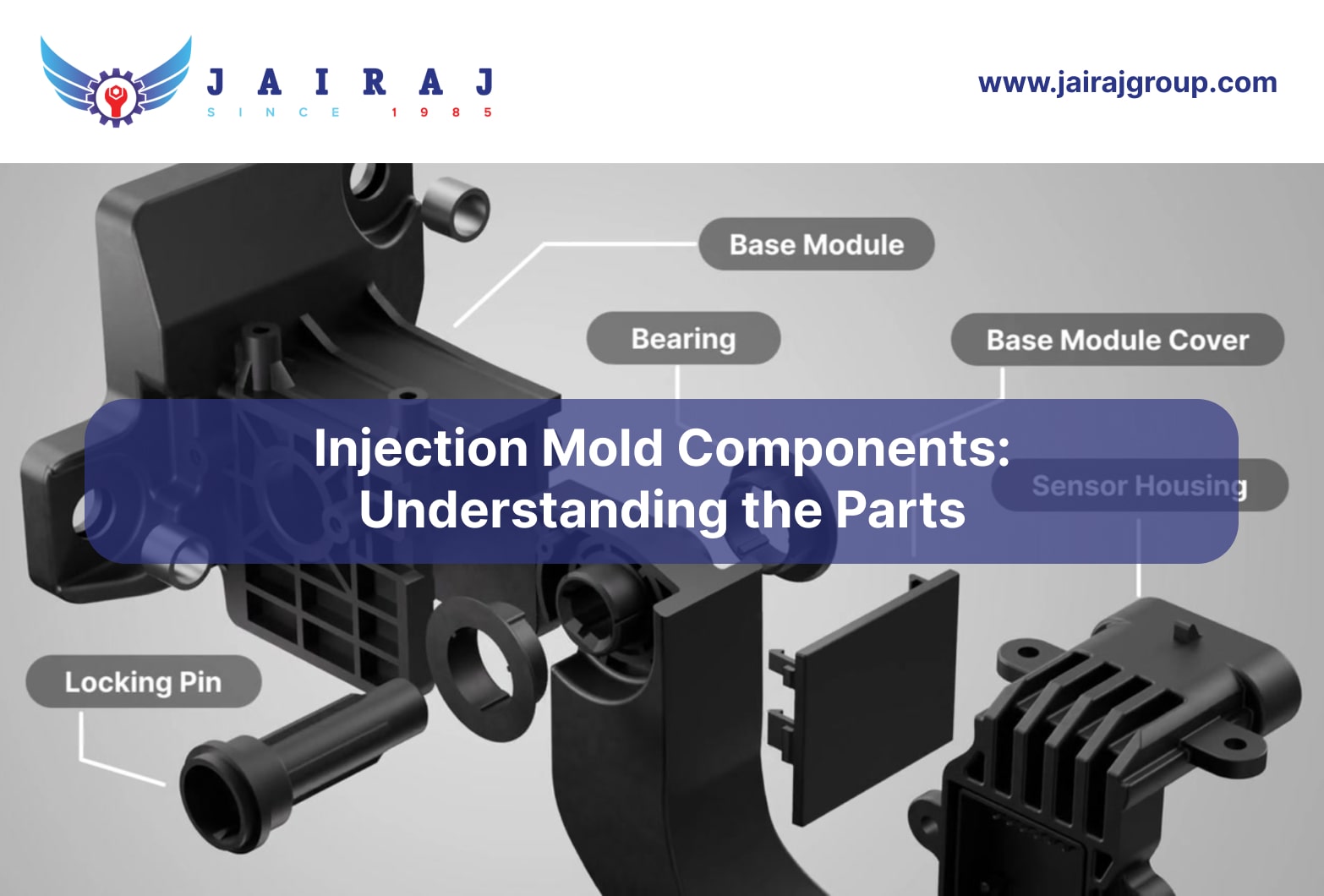
Precision injection mold components are essential for producing high-quality parts across industries such as consumer goods, electronics, medical devices, and automotive. Core, cavity, runners, gates, cooling channels, and ejector systems work together to ensure dimensional accuracy, consistent cycle times, and efficient production.
For program managers and procurement teams, working with capable suppliers, including OEMs and Tier-1 suppliers, is crucial. Tooling quality, material choice, and component design directly impact costs, part consistency, and compliance readiness.
This guide explains key injection mold components, key roles, and criteria for selecting suppliers who deliver durability, precision, and operational reliability.
Key Takeaways
An injection mold is built from multiple functional systems combined into one mold base.
Each part has a specific role, from shaping molten material to cooling and ejecting the final part.
Proper alignment, temperature control, and part removal are vital for maintaining product accuracy and mold longevity.
The mold structure varies slightly depending on whether it is a two-plate, three-plate, or hot runner mold.
To begin, it’s important to understand what injection molding is and how the type of mold affects production.
Understanding Injection Molding and Its Types
Injection molding is an advanced manufacturing technique where molten plastic is injected into a mold cavity under high pressure, then cooled and solidified to form the final part.
The mold has two main sections, the stationary cavity side and the moving core side, which work together to produce accurate and repeatable components.
This process is ideal for producing large quantities of identical plastic parts with precise dimensions, smooth finishes, and minimal waste, making it a key method for modern high-volume manufacturing.
The choice of mold type is critical to achieving efficiency, quality, and production speed. Common injection mold types include:
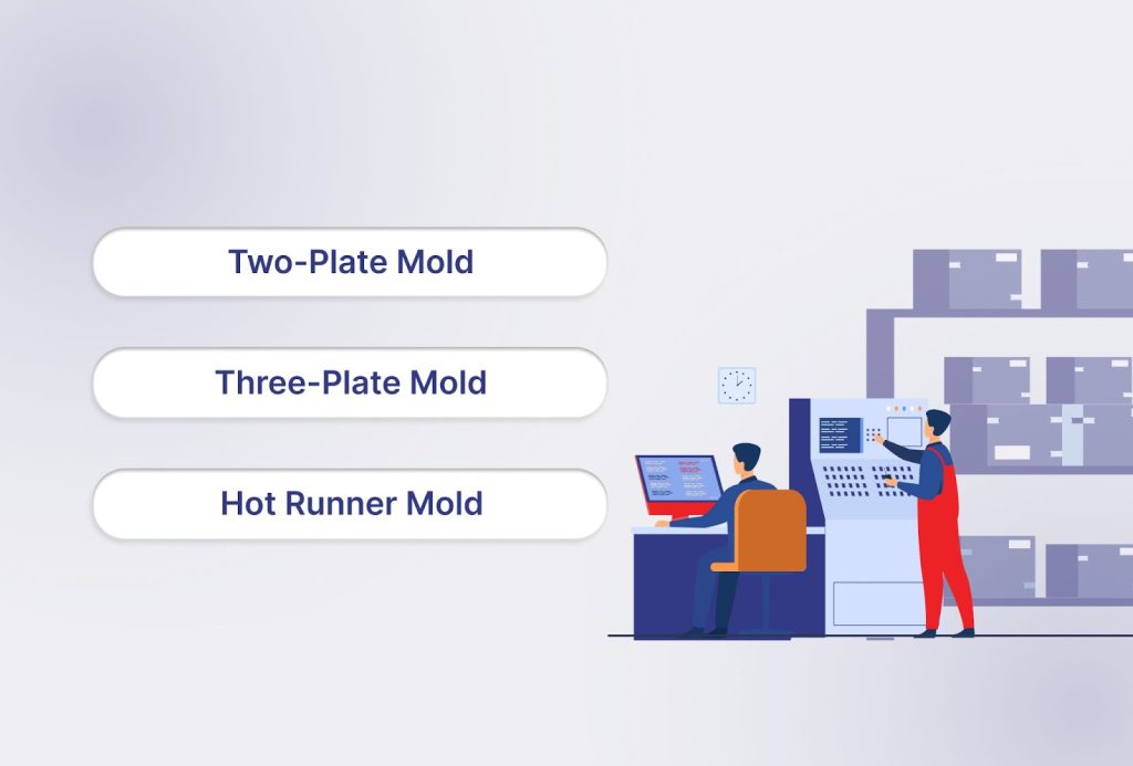
Two-Plate Mold: A simple setup with a cavity plate and a core plate that separate along a single parting line. This design is widely used for most standard molded parts
Three-Plate Mold: Features an additional stripper plate between the cavity and core halves. It allows precise gate placement, eliminates visible gate marks, and works well for larger parts that need multiple gates
Hot Runner Mold: Uses heated channels to keep the plastic molten during injection, removing the need for runners. This approach reduces cycle time, cuts material waste, and supports faster production rates
Before exploring the mold’s subsystems, consider how design and material choices impact performance and longevity.
Design Considerations and Materials for Injection Mold Components
Every injection mold is made up of multiple components, each performing a critical function. The durability, precision, and efficiency of a mold depend not only on its design but also on the materials chosen for each part.
When designing injection mold components, several factors must be considered to ensure long-term performance:
Machinability and Manufacturability: Materials should allow precise machining and finishing while keeping production costs reasonable.
Strength and Rigidity: Components like Brake & Accelerator Pedals, made from Nylon 6/66 and reinforced polymers, withstand high injection pressures without deforming.
Wear Resistance: Parts such as Shockers & Suspension Components use high-performance polymers and tool steels to endure repeated friction and mechanical stress.
Thermal Resistance: Precision Components from Advanced Polymers rely on tool steels and reinforced polymers to tolerate rapid heating and cooling without warping.
Surface Finish: Interior & Exterior Accessories, produced from ABS, PC/ABS, or polymer blends, achieve smooth surfaces for functional and aesthetic quality.
Material Compatibility & Environmental Resistance: Components such as Shockers & Suspension Components use UV-resistant plastics to maintain durability under harsh conditions.
Next, choosing the right material for each mold component depends on the design requirements and production conditions. The following table provides an overview:
| Injection Mold Part | Key Properties | Typical Materials |
|---|---|---|
| Mold Base | Strength, Rigidity, Wear Resistance, Thermal Resistance | Tool Steels (P20, H13), Aluminum Alloys |
| Core | Strength, Rigidity, Wear Resistance, Thermal Resistance, Surface Finish | Tool Steels (P20, H13), Pre-Hardened Steel (4140), Aluminum Alloys |
| Nozzle or Sprue | Strength, Rigidity, Wear Resistance, Thermal Resistance | Tool Steels, Hard Steel Alloys (Nickel, Beryllium Copper) |
| Inserts | Strength, Machinability, Material Compatibility, Thermal Resistance | Metals, Ceramics, Reinforced Polymers, Carbon Fiber |
| Mold Interlocks or Guiding System | Strength, Durability, Wear Resistance | Tool Steels, Hard Steel Alloys |
Also read: Precision Components from Advanced Polymers for Automotive and Aerospace Applications
Now let’s explore the main subsystems of an injection mold and their roles.
Essential Injection Mold Components and Their Key Parts
Injection molds are precision-engineered tools used in plastic manufacturing to produce consistent, high-quality parts at scale. A mold is composed of various subsystems that work together to form, cool, and eject plastic components accurately.
Each part of a mold serves a dedicated function, and together they ensure the mold operates reliably under high-pressure and temperature conditions.
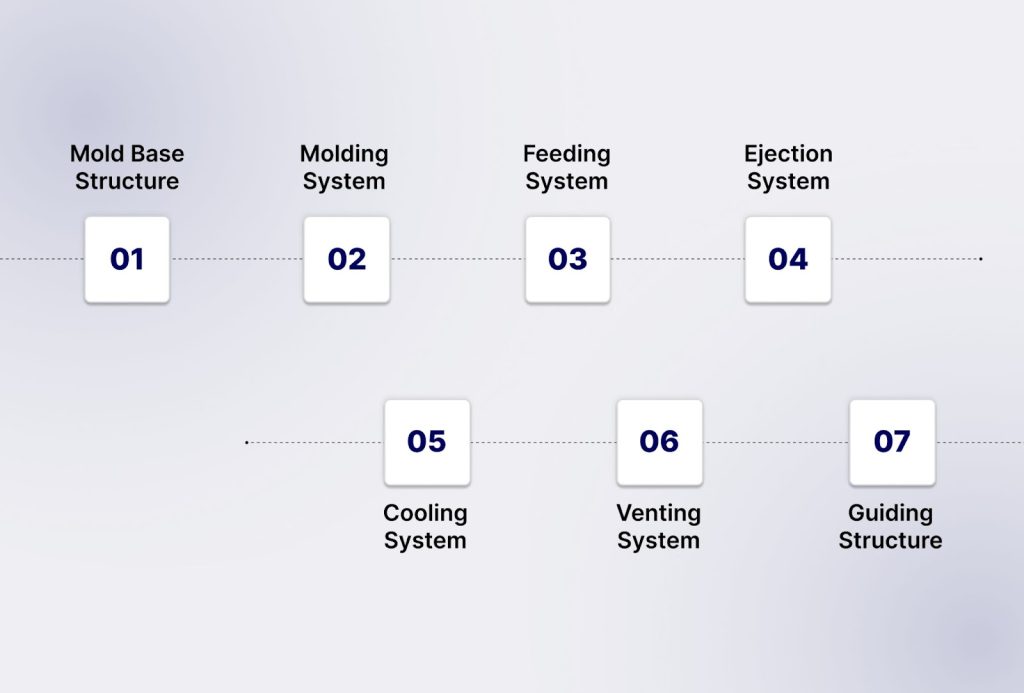
The main subsystems of an injection mold are:
Mold Base Structure
Molding System
Feeding System
Ejection System
Cooling System
Venting System
Guiding Structure
The following sections break down each subsystem, explaining its components, functions, and role in ensuring precise and efficient molding operations.
1. Mold Base Structure
The mold base forms the framework or skeleton of the injection mold. It is typically made from precision steel plates that hold and support all other mold components.
Mold bases are often sourced from specialized manufacturers to maintain tight tolerances, improve efficiency, and ensure long-term reliability.
Common Components of a Mold Base:
Top Clamp Plate: Secures the mold to the stationary side of the injection molding machine, ensuring stability during injection.
A Plate (Cavity Plate): Holds the mold cavity and faces the injection nozzle, forming the exterior geometry of the part.
B Plate (Core Plate): Holds the mold core on the moving side, shaping internal features of the component.
Spacer Block (C Plate): Provides space for the ejection system and determines overall mold height, allowing smooth operation of ejector mechanisms.
Rear Clamp Plate: Fixes the mold to the moving platen of the molding machine, maintaining alignment during opening and closing cycles.
Ejector Retainer Plate: Secures ejector pins in position, preventing misalignment and ensuring smooth part removal.
Ejector Plate: Pushes ejector pins forward to eject the molded part cleanly, supporting consistent cycle times and preventing part damage.
Role: The mold base provides structural support, alignment, and stability for all functional subsystems, including the molding, feeding, ejection, cooling, and venting systems. A well-engineered base ensures long-term tool durability, precise part formation, and reliable production.
2. Molding System
The molding system is the functional component of the mold, responsible for shaping the plastic into its final form. It directly impacts the part’s precision, surface finish, and dimensional stability, making it one of the most critical subsystems.
Key Components:
Mold Cavity: The fixed half of the mold that forms the outer surface of the part. Its accuracy determines the final part’s shape and surface quality.
Mold Core: The moving half that shapes the inner surfaces of the part. Proper alignment with the cavity ensures dimensional consistency.
Slides (Sliders): Move perpendicular or at an angle to release undercuts and complex features that cannot be formed by the core and cavity alone.
Lifters: Mechanisms that eject internal features or undercuts not accessible by slides, ensuring complete part release.
Inserts: Replaceable components embedded in the cavity or core, used for complex geometries or to simplify maintenance and reduce downtime.
Parting Line: The junction where the core and cavity meet; precision here prevents flash and ensures smooth part separation.
Vents in the Cavity/Core: Allow trapped air to escape during injection, reducing defects such as short shots or burn marks.
Role: The molding system defines the part’s geometry, dimensional accuracy, surface finish, and overall quality. Its design and maintenance directly influence production efficiency, repeatability, and defect rates.
Also Read: Plastic Injection Molding: Precision Thermoplastic Components
3. Feeding System
The feeding system delivers molten plastic from the injection molding machine to the mold cavity, ensuring smooth and uniform flow for consistent part quality.
Proper design of this system is critical to prevent defects, reduce cycle time, and improve material efficiency.
Key Components:
Sprue: The main channel leading from the machine nozzle into the mold; it directs molten plastic into the runner system.
Runner: Channels that distribute the melt from the sprue to each cavity, ensuring balanced flow.
Sub-Runners: Branch channels in multi-cavity molds that help maintain uniform pressure and fill across all cavities.
Gate: The entry point where the molten plastic enters the cavity; its size, shape, and location influence filling efficiency, part quality, and ease of ejection.
Cold Slug Well: Captures the first cooled portion of molten material (slug) to prevent it from entering the cavity and causing defects.
Hot Runner (optional): Maintains molten plastic temperature within the runners, reducing waste and improving cycle times.
Sprue Puller (optional): Mechanism to remove the solidified sprue cleanly from the mold.
Role: The feeding system ensures uniform melt distribution, proper cavity filling, and defect-free parts. A well-designed feeding system improves cycle efficiency, reduces material waste, and supports consistent part quality across production runs.
4. Ejection System
Once the part has solidified, the ejection system removes it from the mold efficiently and safely. A properly designed ejection system ensures smooth part release without causing deformation, surface damage, or cycle delays.
Common Components:
Ejector Pins: Push the molded part out of the cavity; come in various diameters and materials for different part geometries.
Ejector Plate: Transfers motion from the mold actuation system to the ejector pins.
Return Pins: Reset the ejector system after each cycle to prepare for the next shot.
Air Ejectors or Stripper Plates (Optional): Used for delicate or large parts to avoid scratches or deformation.
Role and Importance:
Ensures consistent removal of parts without defects.
Reduces cycle time by enabling faster part release.
Minimizes wear on the mold and extends tool life.
Supports high-volume production while maintaining quality and repeatability.
Plays a key role for OEMs and Tier-1 suppliers to meet tight program timelines and reduce scrap.
5. Cooling System
The cooling system controls mold temperature to solidify parts quickly and uniformly, ensuring dimensional accuracy and consistent cycle times.
Typical Components:
- Cooling Channels: Drilled passages within mold plates that circulate water or oil to remove heat efficiently.
- Baffles or Bubblers: Direct cooling fluid to hard-to-reach areas, ensuring even temperature distribution.
- Cooling Connectors: Interface points for water or oil supply and return.
- Thermal Sensors (Optional): Monitor temperature for real-time process control and consistent cooling.
- Sprue and Runner Cooling: Channels specifically targeting the sprue and runners to prevent heat buildup.
Role:
Reduces cycle time by accelerating part solidification.
Supports uniform cooling across complex geometries, improving overall part quality and repeatability.
6. Venting System
The guiding structure ensures accurate alignment of mold halves during closing, which is critical for maintaining part precision, minimizing wear, and preventing flash. Proper guidance also reduces downtime, improves mold lifespan, and ensures consistent part quality across production cycles.
Typical Components:
Guide Pins: Align the core and cavity precisely during mold closing.
Guide Bushings: Provide smooth movement of the guide pins while reducing friction and wear.
Leader Pins: Maintain accurate alignment in large or multi-cavity molds.
Shank Pins: Support additional alignment where high precision is required.
Alignment Sleeves: Ensure concentric closure of mold halves, especially for complex geometries.
Support Plates: Add stability to the guiding system under high injection pressures.
Role:
Maintains precise alignment between core and cavity to ensure dimensional accuracy.
Prevents flash and defects along parting lines caused by misalignment.
7. Guiding Structure
The guiding structure ensures accurate alignment of mold halves during closing, which is critical for part precision, surface finish, and mold longevity.
Typical Components:
Guide Pins: Positioned on one half of the mold to align with corresponding bushings on the other half.
Guide Bushings: Receive guide pins and ensure smooth, precise movement during mold closure.
Leader Pins: Additional alignment elements for larger or multi-cavity molds, providing extra stability.
Support Plates (Optional): Reinforce alignment in heavy or complex molds to prevent deflection under pressure.
Role: Maintains precise alignment between the core and cavity, preventing flash, uneven wear, or misalignment that could compromise part quality. Accurate guiding ensures smooth mold operation, prolongs tool life, and supports consistent production.
Also read: How to Choose the Right Plastic Product Supplier for Automotive & Industrial Components
To meet high-stakes program requirements, JaiRaj Group focuses on:
High-Precision Injection Mold Components for OEMs & Tier-1s
Reliable injection mold components are essential to the performance of critical automotive systems. A dependable manufacturing partner helps control production costs, ensure supply stability, and maintain launch schedules without disruptions.
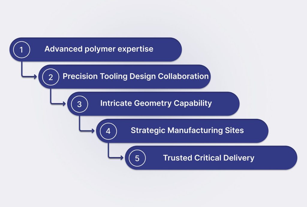
JaiRaj Group has structured its expertise around five core strengths that support the demanding requirements of automotive OEMs and Tier-1 suppliers:
1) Advanced polymer expertise
Handling a wide spectrum of materials like PA6/66, PBT, POM, PC/ABS, and high-performance composites, JaiRaj enables teams to meet strength, weight, and durability targets while managing raw material volatility. Its in-house development cell fast-tracks validation of alternate resins to keep programs running smoothly.
2) Precision tooling with design collaboration
Tooling and product engineering teams at JaiRaj work closely with customers from the concept stage, using advanced simulation to predict flow, cooling, and shrinkage. This approach minimizes tooling rework, shortens qualification cycles, and ensures every molded component meets tight dimensional tolerances.
3) Capability to produce intricate geometries
Expertise in insert molding, two-shot molding, overmolding, micro-molding, and gas-assisted molding allows JaiRaj to manufacture complex parts with high accuracy. This process range helps consolidate multiple features into single parts, reduce assembly operations, and improve long-term reliability.
4) Strategically located manufacturing sites
Plants in Faridabad, Manesar, Aurangabad, Sanand, and Rudrapur place JaiRaj close to major automotive clusters. This presence reduces transport costs, accelerates delivery, and ensures backup production options during supply disruptions.
5) Trusted delivery across critical applications
With 35+ years of experience and certifications including IATF 16949, ISO, and CE, JaiRaj has supplied precision mold components for vital automotive functions, including:
For purchasing teams, JaiRaj offers more than just parts, it provides a dependable partnership built on quality assurance, supply continuity, and operational efficiency.
Conclusion
Injection molding is a central pillar in automotive manufacturing. It affects not only production costs but also launch schedules, regulatory approvals, and the strength of supply networks.
For OEMs and Tier-1 suppliers handling large-scale programs worth millions, the priority is not learning how injection molding functions but managing it in a way that reduces risk and builds competitive strength.
Companies that focus on material consistency, systematic tooling processes, rigorous compliance systems, and broad supplier networks often achieve:
Reliable total cost control by cutting hidden losses from scrap, transport, and tooling corrections.
Quicker market introduction with supplier-supported DfM inputs and smoother PPAP sign-offs.
Stable supply chains that stay operational during resin price changes and regional challenges.
If you are preparing a new project or shifting existing components, connect with JaiRaj Group for a Design for Manufacturability (DfM) review or plan a plant visit at Manesar, Sanand, or Aurangabad.
Reach out to JaiRaj Group to discuss your requirements.
FAQs
1. What are the primary components of an injection mold?
An injection mold typically consists of a core, cavity, ejector system, runner system, and cooling channels. The cavity forms the exterior of the part, while the core shapes its interior features. Runners deliver molten plastic to the mold cavities, and the cooling system regulates temperature to solidify parts efficiently. The ejector system pushes the molded part out after cooling.
2. How does the core and cavity influence part quality?
The core and cavity determine the part’s shape, surface finish, and dimensional accuracy. Any misalignment or wear in these sections can cause defects such as warpage, flash, or inconsistent thickness. Precision machining, proper material selection, and regular maintenance help maintain part consistency throughout production runs.
3. What role do runners and gates play in molding performance?
Runners and gates control how molten material flows into the mold cavity. Their size and layout affect fill balance, pressure distribution, and cycle time. Well-designed runner systems minimize material waste, prevent air traps, and reduce stress in molded parts, resulting in higher production efficiency and better part integrity.
4. Why are cooling channels critical in mold design?
Cooling channels manage the temperature of the mold during each cycle, which directly impacts cycle time and part quality. Uneven cooling can cause shrinkage variations, surface defects, and dimensional instability. A properly engineered cooling system ensures uniform temperature control and faster part solidification.
5. What does the ejector system do in an injection mold?
The ejector system removes the finished part from the mold after it cools. It usually includes ejector pins, plates, and return mechanisms. If the ejection system is not properly designed, parts may stick, deform, or get damaged during removal, leading to downtime and scrap.